ELECTRONIC REPAIR
Repairing something electronically would seem to most folks, to be totally out of reach. Most people wouldn't know where to even start. On this page, I am going to give you a good beginning in regards to repairing cables and low-voltage electronic circuits. With that said, you need to read this first:

Disclaimer - If you are reading this page, you may not know how to repair high-voltage/amperage circuits. I am in no way encouraging you to do so. Items like power supplies in most circuits and tube amplifiers can have very high voltage/amperage involved. Even with certain circuits unplugged, high voltage can be stored within their components, and if you are not for sure how to safely discharge these components, you could be seriously injured or killed. Work on this stuff at your own risk.
DEFINITIONS OF TERMS
You may see a word on this page that you are not even for sure what it means. I found a pretty decent online dictionary of electronic terms you may access if you need help. I chose this particular version because it defines many of these terms as it relates to audio:
OHMS LAW
Before you start all of this, it would be good for you to check out Ohm's Law. It is important to at least familiarize yourself with it before you proceed.
ELECTRONIC COMPONENTS
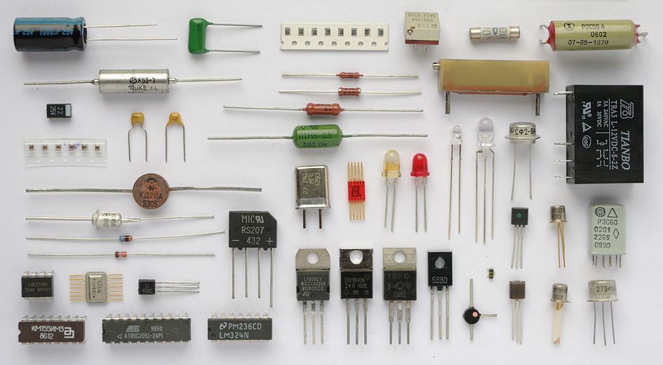
What in the tarnation are all of these doohickers? I'm bout to tell ya...
Resistors <<<<< you should totally click this
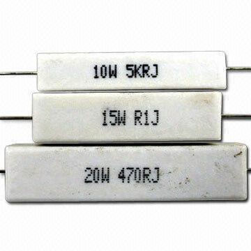
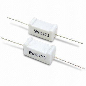
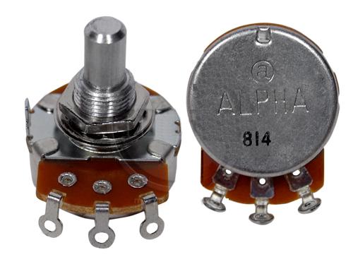

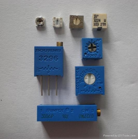
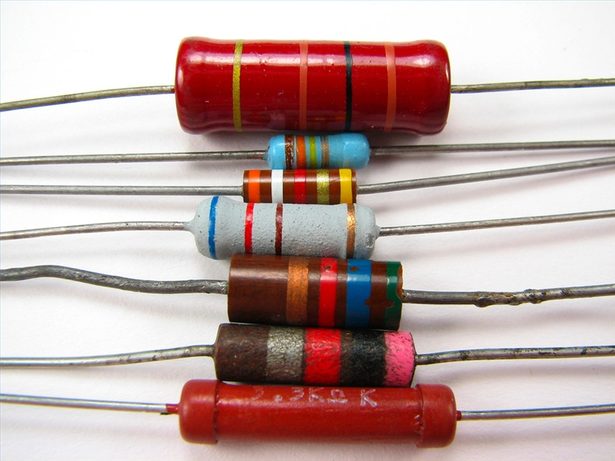
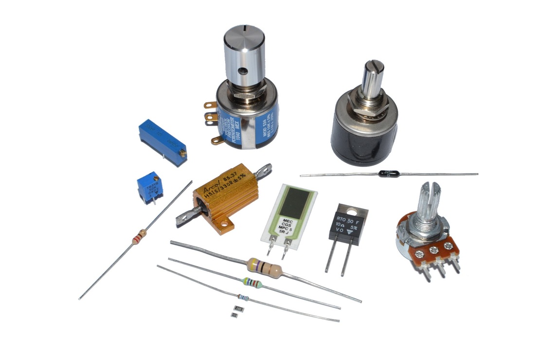
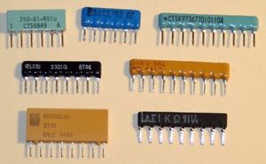
The above pictures show different types of resistors. There are more than this, but these are the most common type of resistors used in audio.
When looking at a schematic diagram, resistors will be represented most commonly by these symbols:
When looking at a schematic diagram, resistors will be represented most commonly by these symbols:
Capacitors <<<<< You should totally click this too!

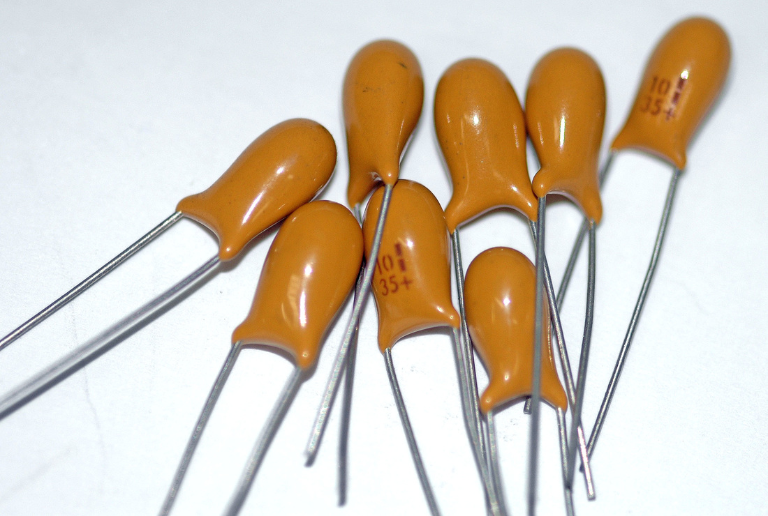

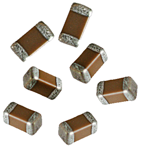

The above pictures show different types of capacitors. There are more than this, but these are the most common type of capacitors used in audio.
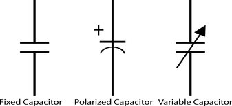
When looking at a schematic diagram, capacitors will be represented most commonly by these symbols:
When looking at a schematic diagram, capacitors will be represented most commonly by these symbols:
Have you ever had something that wouldn't come on when you tried powering it up, or when it is powered up, the audio device you are using starts to act goofy? There are multiple reasons why this can happen, but one of the most common, are leaky & faulty electrolytic capacitors in the power supply or other places. Here is a picture of faulty capacitors:
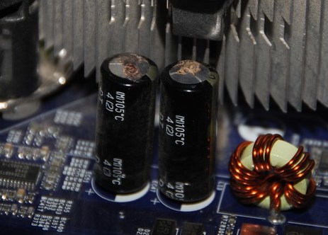
Notice the nasty brownish-black stuff coming out of the top of these electrolytic capacitors. This means that the capacitor is faulty, and will need to be changed.
Now, on low-voltage types of devices - like keyboards, drum machines, guitar pedals, speaker crossovers (with the speaker unplugged from the amplifier), etc - these are easily replaced, and there isn't that big of a danger in replacing them. Notice the plus (+) signs on one side, and the solid (-) lines on the other on the PCB. You will notice minus signs on polarized electrolytic capacitors such as these. That's right, you have to match negative to negative & positive to positive on polarized capacitors when placing new ones back in the holes of the printed circuit board. Before even attempting to replace them, look at the voltage rating on the sides of the capacitors (cans). The two most common capacitors in audio are: 16v (16 volts) & 25v (25 volts). 16 volts and 25 volts are non-lethal voltages, and these types of caps (short for capacitors in electronic technicians speak) can be easily replaced if you have a de-soldering iron and some patience.
**Warning: Do not try replacing electrolytic capacitors (like shown in the above picture) on any electronic device that contains high voltage/amperage. Even with the device unplugged, capacitors can still hold a charge waiting to bite its next victim. This kind of work is reserved for experienced electronic technicians only. For example: a guitar tube amplifier can have up to 450 volts stored in its capacitors. This is more than enough to kill you in an instant. I have personally replaced electrolytic capacitors in tube amps on numerous occasions, but I know how to safely discharge them without incident because I have been working on them for close to 20 years. If you are not an experienced tube amplifier repair technician, or you are not for sure what you are doing, don't chance it!
|
Diodes <<<<< yes, this is clickable as well
|
|
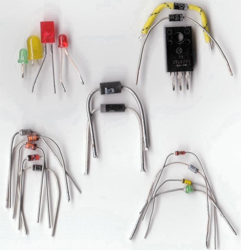
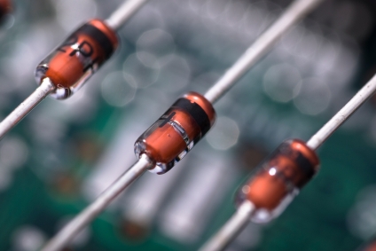

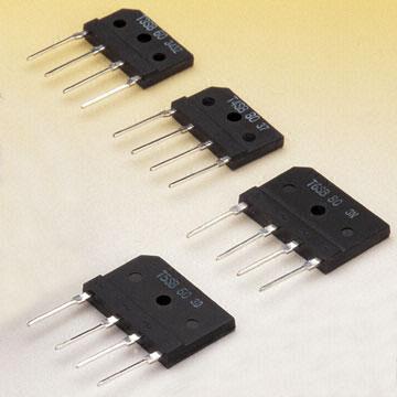
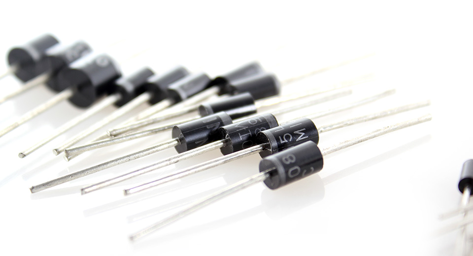
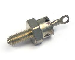
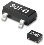
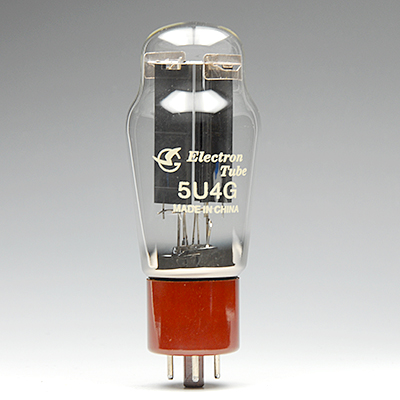
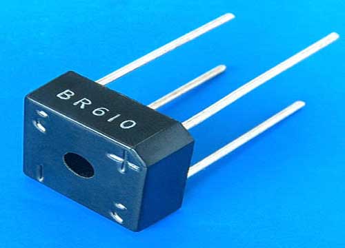
The above pictures show different types of diodes & rectifiers. There are more than this, but these are the most common type of diodes used in audio.
When looking at a schematic diagram, diodes will be represented most commonly by these symbols:
When looking at a schematic diagram, diodes will be represented most commonly by these symbols:
Transistors & Opamps <<<<< you can click either one of these
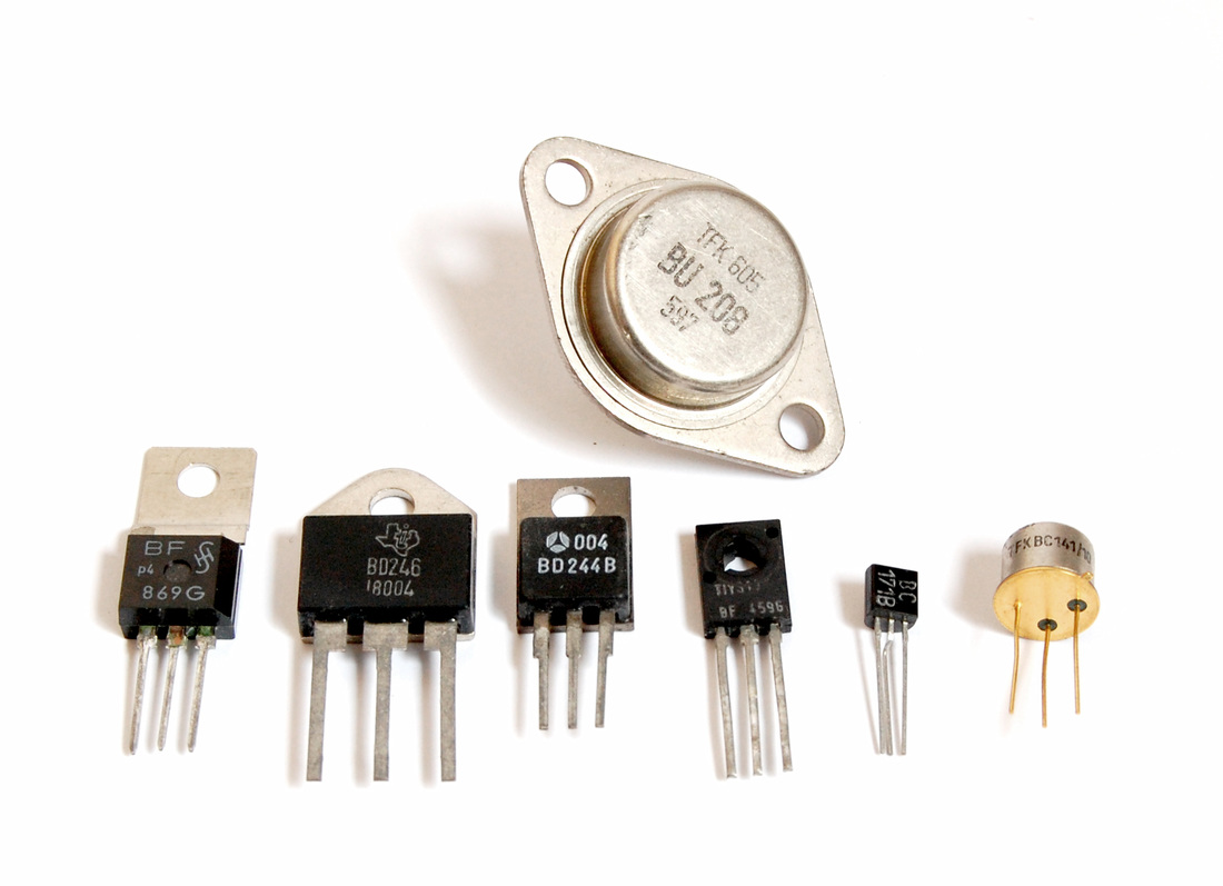
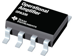
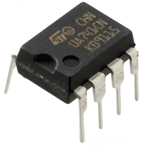
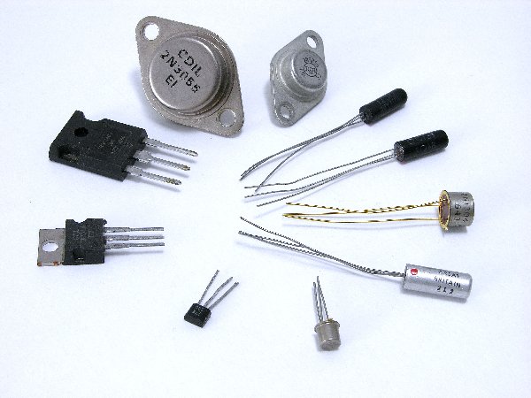
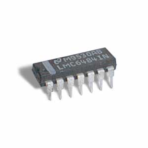
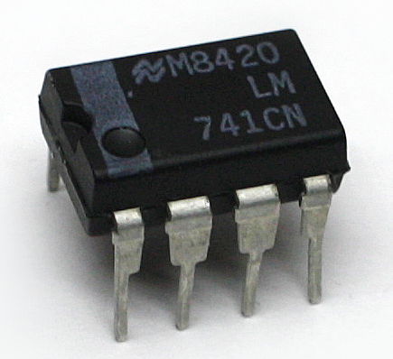
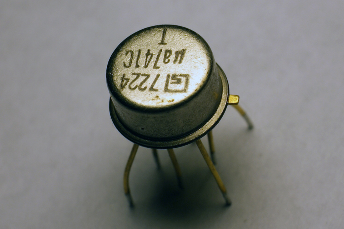
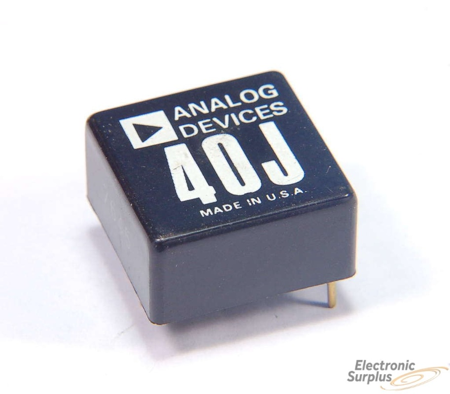
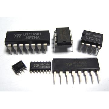
The above pictures show different types of transistors and opamps (operational amplifiers). There are more than this, but these are the most common type of transistors & opamps used in audio.
When looking at a schematic diagram, transistors will be represented most commonly by these symbols:
When looking at a schematic diagram, transistors will be represented most commonly by these symbols:
When looking at a schematic diagram, opamps will be represented most commonly by this symbol or something similar:

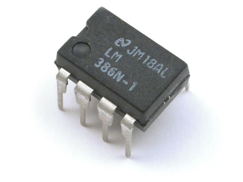
Here's something to keep in mind - an opamp is basically a bunch of little bitty transistors placed into one small component case to save room. Here is what a 741 opamp would look like if it was comprised of regular sized transistors and resistors:
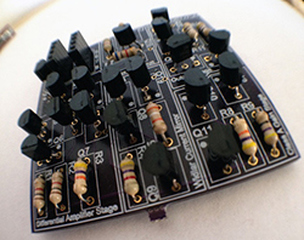
An opamp is made up of a lot of miniature transistors and resistors...
Transformers <<<<< yup, you probably know the routine now...
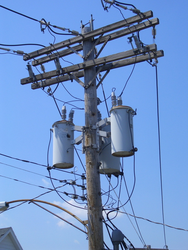
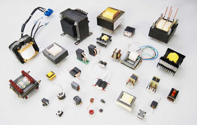
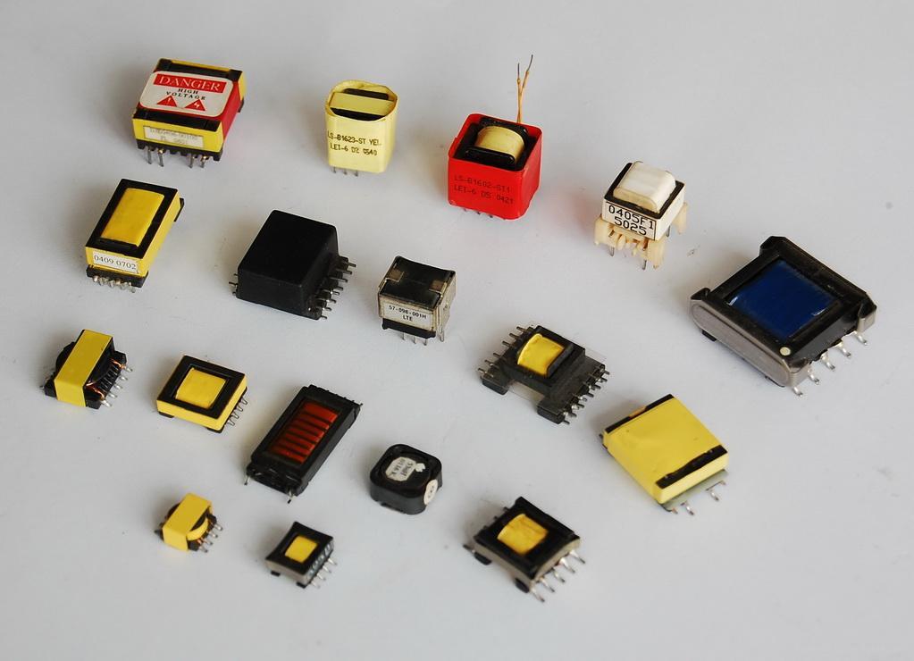
The above pictures show different types of transformers.
When looking at a schematic diagram, transformers will be represented most commonly by these symbols:
When looking at a schematic diagram, transformers will be represented most commonly by these symbols:


Putting It All Together
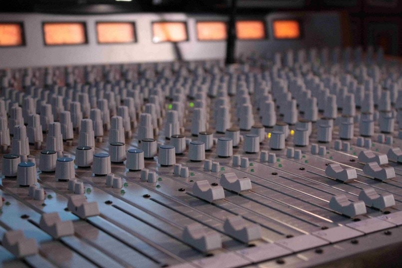
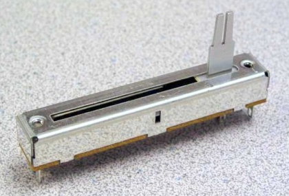
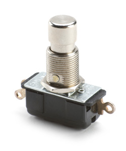
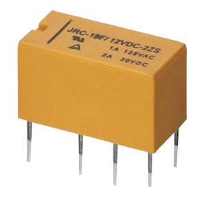
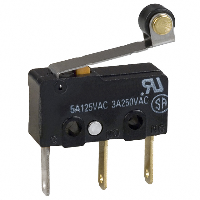
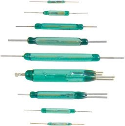
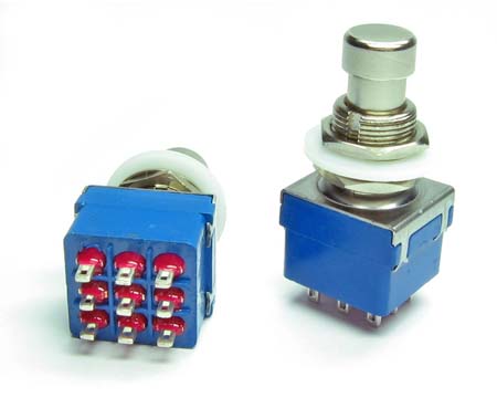
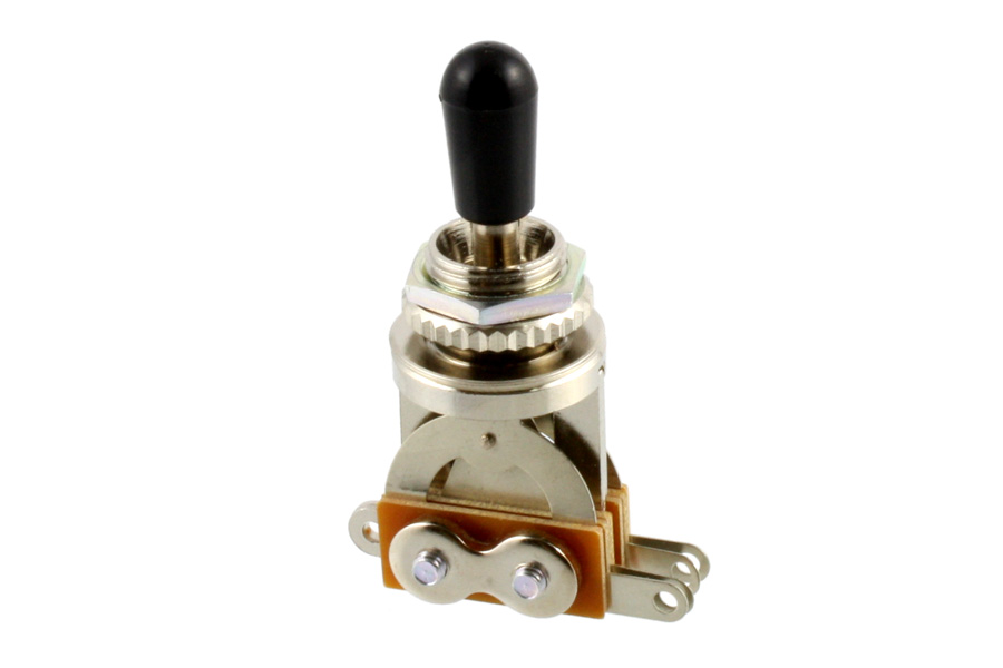
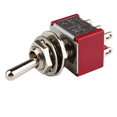
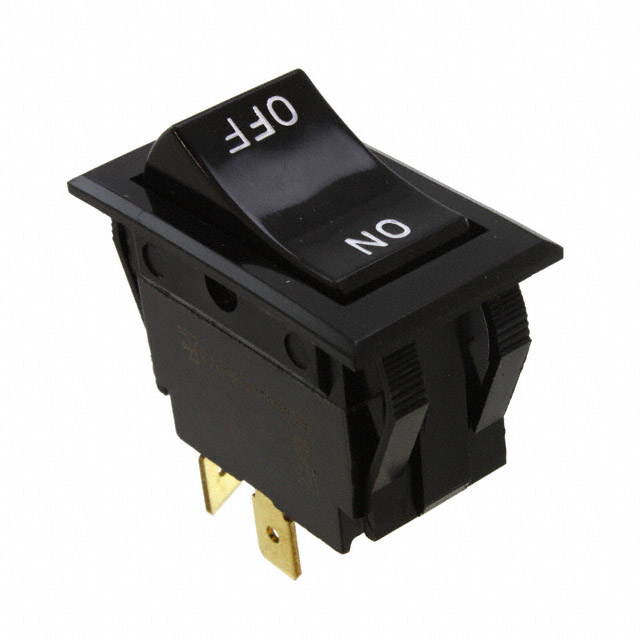
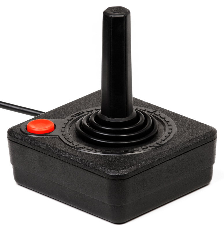
So, now that you know what each component is, can you spot what is what on this mixing console? All of the knobs are potentiometers (variable resistors), and the faders are Liner Resistors. Do you see the light emitting diodes aka LEDS? What about the switches? Pretty cool huh? BTW: notice the concentric potentiometers? A concentric pot is two potentiometers built into one.
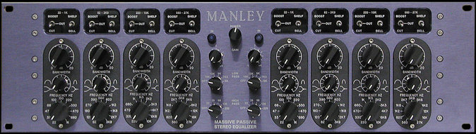
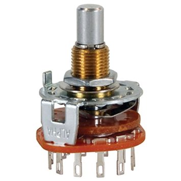
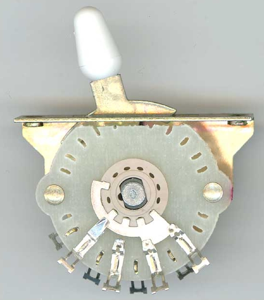
The Manley Massive Passive is a great example of a unit with combined technology to achieve a similar effect on its' face panel. A lot of Manley gear will have a rotary switch with multiple value resistors and/or capacitors for the controls, rather than just potentiometers. This allows the user to select exact frequencies (as shown on the very bottom knobs), rather than making a guess with non-descript labeling.
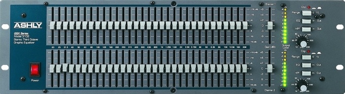
A dual 31 band EQ. Do you see that massive amount of slide potentiometers? I see some light emitting diodes in there as well as some switches.
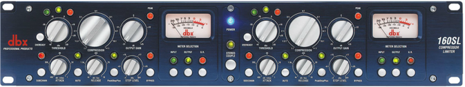
All kinds of potentiometers, switches, l.e.d.'s, and even a couple of VU Meters.
Look at all that switches, knobs, and led goodness!
Supplies
To do any type of electronic repair, you will need some supplies. Here is a short list of what you'll need:
1. Soldering Iron(s): 40 watt, 60 watt, 100/250 watt gun. If you can only afford one, I would get the 40 watt.
2. Rosin Core Solder: Get the 60/40 tin-lead type. Don't buy the silver solder. Do NOT buy acid core solder.
3. A solder sucker or de-soldering iron (I much prefer the de-soldering iron).
4. A set of 3rd hands
5. A soldering iron stand with a tip cleaner
6. Wire strippers - The automatic kind are awesome.
7. A razor knife.
8. Hook-up wire
9. Heat Shrink
10. Electrical Tape
11. Soldering Iron Stand
Note: When purchasing a soldering iron, make sure you get a decent brand with the ability to find replacement tips easily.
HOW TO SOLDER
This is the main thing that keeps people from repairing their own cables and such. Most people just don't know how to solder! Here are some excellent videos to help you master it:
Now, some of these videos are outdated in some of the content, but the basics of soldering is pretty well explained within them. You see too many Bifurcated terminals anymore or TO-5 based IC's, but just watching the soldering techniques will help you in your new soldering endeavor. The Cup terminals, can still be found on XLR (microphone) connectors.
HOW TO USE A MULTIMETER
SCHEMATICS & WIRING DIAGRAMS
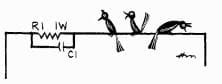
Once you know what the symbols stand for, you can pretty much build most anything (with the combined knowledge above).
Check out this high-tech rendering in Microsoft Paint of this schematic. Ha! This shows the basic stages of a typical musical circuit. Did you know that you can actually "voice" this pedal to sound different? You can have 2 silicone diodes, and then replace the 3rd one with a 1n34a germanium diode. This will give the circuit a little more headroom and smoother clipping. You could add another clipping stage and blend between the two with a potentiometer as a blend control. You could switch in numerous types of diodes for different voicings. The sky is the limit.
Electronic Reference Material
Figuring Out Resistor Color Codes
Resistors will have a color code on each one (typically). This color code will tell you its value in ohms. If you look at the above schematic, you may see a 10K resistor. If you have a lot of resistors in a pile, how would you tell what value that resistor was? You could do it a couple of ways:
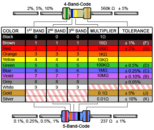
So, if I was looking for a 10k resistor, I would choose a resistor that had the colors Brown - Black - Orange. This would equal 10k, and would look like this:
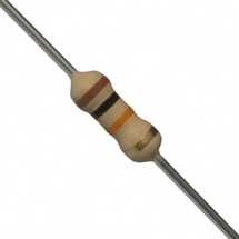
This is a 10k resistor. Notice the Gold band in the 4th position? This means that this resistor is within a 5% tolerance of accuracy. A 10k resistor could actually be 9.5k or even 10.5k or anything close to 10k. This is normal, and usually this small of a variation will not make a big difference in how the circuit behaves. This is why though, that two units of the exact same make and model may sound slightly different!
If you have studied the above chart, and are still confused on how to use it, you could also use an online color code calculator, such as this one. Super handy! And if all else fails, you can also use a multimeter to figure out the resistance of a resistor as shown in the above video.
Transistor Pins have a particular configuration according to what type. Here's a Super Useful Transistor Pin-Out Chart.

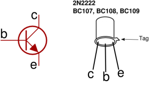
This is an example of a transistor with its own pin-out. Not all transistors will have this pin-out or configuration. That's why that handy dandy chart referenced above is so cool. [ e = emitter b=base c=collector ] Notice in these two above examples, the pins are configured totally differently.
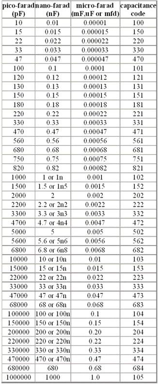
Capacitor Code Chart
A lot of ceramic disc and mylar capacitors will have a 3 digit code to let you know its value. Capacitors most commonly are rated in microfarads (uf), nanofarads (nf), and picofarads (pf). So when looking at a capacitor, how do you know its value? Here is a chart to help you figure that out. And yes, microfarads will show up as " uf " in most schematics because it is hard to type the fancy " µ " symbol on a keyboard (alt-230).
So, what is the value of this ceramic disc capacitor:
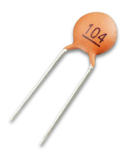
If you look at the code at the right of the chart, we can see that "104" is a .1µf (microfarad) capacitor
XLR Pin-Outs & Other Tidbits
When soldering an XLR plug or jack, it is important to make sure you use the appropriate pin configuration. **Cool Tip Alert: When soldering an XLR connector, you will notice that they usually will feature cup terminals. Heat your cup terminal first with your soldering iron, and fill the cup with molten solder first. Then when you get ready to solder a pre-tinned wire to the cup terminal, you just heat the cup up from underneath (heat rises), and place your wire into the cup. Wait just a few seconds for the solder on the pre-tinned wire to meld in with the solder in the cup terminal. By the way, the wire should be the same length as the cup terminal so that you do not have extra wire sticking out from beyond the terminal itself.
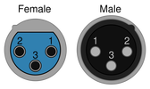
Another Cool Tip Alert: You really don't have to remember the above pin-out. Almost every quality XLR connector and/or jack will have the number of each pin molded in the plastic for reference. Pin 1 is always shield (the wire with no insulation). Pin 2 is always hot (usually red colored wire on most microphone cables). Pin 3 is Cold (usually black on most cables). Really the color of the wires is not important, as long as you match colors to the opposite side pin-wise. Meaning...if you have blue on pin 2 on one side, make sure blue is soldered to pin 2 on the other side, and so on. The cable doesn't know the difference. Just make sure you match the colors to the pins on each side. Also, on another note: The female side will be opposite of the male side, kind of like a mirror.
Another Cool Tip Alert: You really don't have to remember the above pin-out. Almost every quality XLR connector and/or jack will have the number of each pin molded in the plastic for reference. Pin 1 is always shield (the wire with no insulation). Pin 2 is always hot (usually red colored wire on most microphone cables). Pin 3 is Cold (usually black on most cables). Really the color of the wires is not important, as long as you match colors to the opposite side pin-wise. Meaning...if you have blue on pin 2 on one side, make sure blue is soldered to pin 2 on the other side, and so on. The cable doesn't know the difference. Just make sure you match the colors to the pins on each side. Also, on another note: The female side will be opposite of the male side, kind of like a mirror.
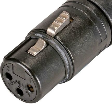
Here is a VERY large picture of a female XLR connector. Check out the imprinted numbers on each pin hole. When you take this connector apart to solder it to a cable, you will see the imprinted numbers on that inside by the cup terminals as well.
WHAT SHOULD BE IN A TECH'S TOOL BAG (IDEALLY)
|
Every tech/engineer should have a plethora of tools available to them at all times. Engineering is more than just pushing buttons and pushing faders. You need to learn all facets of your gear, and how to service and maintain it all. Bad stuff can happen at the worst moment possible when running sound. Are you ready for it? Here is an exhaustive list of supplies that every sound man/woman should have in their arsenal for such occurrences:
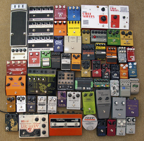
1. Cables - All Kinds!
|
|
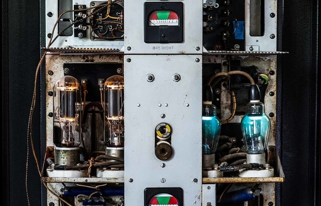
All About Tube Amplifiers
**Disclaimer: If you don't know what you are doing with a tube amplifier, you may be at risk for getting killed. That's right. A tube amplifier can have up to 450 volts stored in its filter capacitors (and everything attached to them as well); even with the amplifier unplugged. Getting killed is not fun. At the very least, you could have a numb arm and lose control of your bowels (which isn't fun either). I provide these videos so that you'll have a decent understanding about how they work - not so you can go poking around in the circuit to discover the ill effects of electricity! - HOW'S THAT FOR A DISCLAIMER?
|
|
|
|
|
